
Let’s describe the ventilation control method(algorithm) of the Enasan Tunnel. Ventilation control is divided into two modes: Normal and Emergency (in case of fire). Maintaining a normal tunnel environment, saving energy, and ensuring safety in an emergency are the main objectives of ventilation control methods.
The cross-flow ventilation system adopted in the Enasan Tunnel is superior in safety in an emergency (in case of fire), and it is known that the normal ventilation control method can be applied almost in an emergency (in case of fire). Therefore, the ventilation control method(algorithm) is mainly studied for normal operation.
Let’s recap the ventilation system of Enasan Tunnel once again. The Enasan Tunnel is 8469m long and has ventilation facilities equipped with blowers and exhaust fans at both portals/entrances. In the middle of the tunnel, there is a vertical shaft and inclined shaft that can ventilate the air and exhaust the air, and there are two ventilation room at the connection between them and the main shaft. A total of four of them are responsible for separate ventilation actions.

In Enasan Tunnel, the vehicles enter from both portal and emits pollutants (Soot, CO, etc.) inside the tunnel. The air inside the tunnel containing this pollutant is discharged out of the tunnel by an exhaust fan, and fresh air is introduced into the tunnel by an air blower. In normal times, the air supply volume and exhaust volume of each section are identical, and a minimum air volume is set to maintain the pollution concentrations standards for that section.
After returning from my first business trip from USA and debriefing session at the central Research Laboratory (June 28,1974), I visited the deputy chief of the Japan Highway Public Corporation and the section chief in charge of the construction office to thank them for introducing the Lincoln Tunnel and to report on the status of the Lincoln Tunnel. At that time, the section chief in charge recommended that the Kanmon Tunnel be used as a reference, and on July 25 and 26, 1974, I had the opportunity to observe the ventilation operation situation with Enasan project members. The Kanmon Tunnel (3461 m), like the Lincoln Tunnel (about 2500 m), had a cross current ventilation system, and the combined system of changing the number of poles of the induction motor and variable rotor blade angle was adopted to control the airflow of ventilation fan. In addition, as in the Lincoln Tunnel, a program operation with constant airflow for one hour was adopted to take into account the traffic change pattern, and manual operation was added in which the operator adjusted the airflow when the pollution concentration in the tunnel was below the standard.
Following the Kanmon Tunnel or Lincoln Tunnel method is a viable option with low risk because it is based on actual results. However, in the Enasan tunnel, a variable speed axial flow fan with a thyristor motor replaced the rotor blade variable type axial flow fan used in conventional tunnels. The variable speed axial flow fan has few restrictions on changing the airflow, and the conventional control period of one hour can be shortened. Therefore, they chose to develop a new ventilation control that would keep the pollution concentration in the tunnel within the standards and minimize the amount of power consumption.
I studied optimal control during my master’s degree, and with reference to the approach used at this time, firstly derived a concise nonlinear differential equation as a mathematical model for ventilation in the Enasan tunnel. From this nonlinear differential equation, a linear difference equation effective in the vicinity of the reference pollution concentration was obtained, and the ventilation control method was expressed in the form of optimal regulator control.
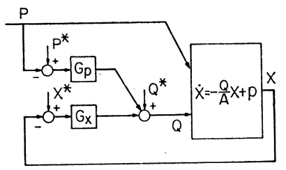
By applying this process, the ventilation control can be diagrammatically represented in the form of optical regulator control, which combines traffic feed-forward control and pollution concentration feedback control as shown in figure below.
| P* Standard generated pollutionX *Reference pollution concentrationQ*Reference ventilation volume | Q(k) Ventilation volumeX(k) Pollution concentrationP(k) Emitted concentration |
| Gx(k), GP(k) Feedback Gain | |
This optimal regulator control was combined with the Enasan tunnel ventilation simulator and its effectiveness was confirmed by repeated numerical experiments. At that time, a large computer that could handle this calculation was located at the Osaka Umeda computer center, so had to travel many times from the central laboratory in Amagasaki.
The calculation results showed that a control period of 10 minutes, instead of the conventional 1 hour, was effective in two respects: maintaining pollution levels and saving energy. The resulting control period of 10 minutes is still used in many tunnels in our country. The control algorithm was written in FORTRAN language. It was installed On Mitsubishi Electric’s M60 industrial computer (a 16-bit machine) and delivered to the Enasan tunnel.
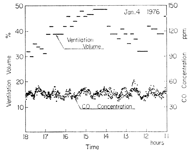
We compiled this method into research paper and submitted it to the Journal of the Japan Society of Civil Engineers. I fondly recall that despite my background in Electrical engineering, I hurriedly joined the Japan Society of Civil Engineers to submit this paper. In addition, actual operations result at the Enasan tunnel is cited to show that the pollution concentration (CO) was kept constant.
(Continue)
References:
1) Mitsubishi Electric Technical Report December 1975 (1975) Genji Ueki, Shizuo Kurita, Ichiro Nakahori, and others, “Expressway Tunnel Ventilation System: Electric Motors and Control Systems,” p 772.
2)Japan Society of Civil Engineers’ Annual Report No. 265, September 1977, Genji Ueki, Ichiro Nakahori, Kazuo Maeda, “New Ventilation Control Law in Long Major Road Tunnels,” p 83.